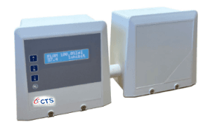
CTS-102 CONTROLLERS
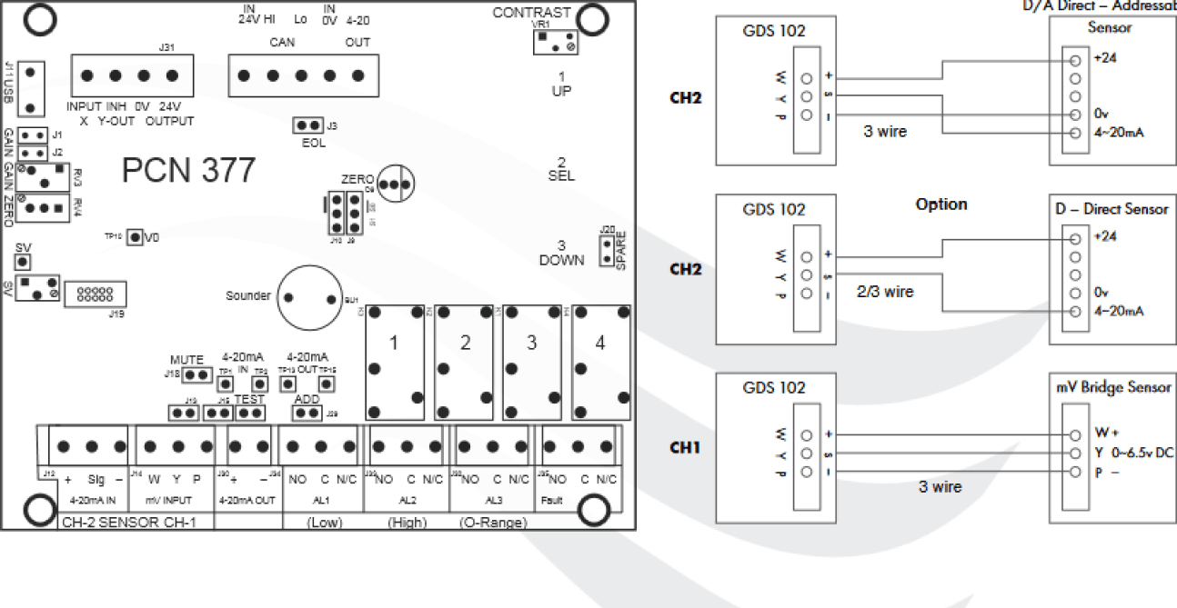
Two detector channels:Channel 1: mV Bridge Channel 2: 4~20mA
Traffic light status display
Data logging
Three alarm stages + relays
4~20mA analogue output
Front panel access to set up and maintenance of parameters
Weatherproof
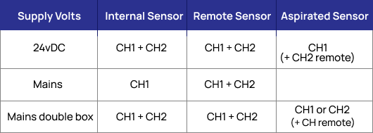
Internal or remote sensor options
Options: Cable entry 25mm, 3/4 NPT
Aspirated sensor option
A fixed dual sensor gas alarm unit that meets the requirements for economic and reliable monitoring of gas levels in a wide range of environments, from commercial premises through to heavy industrial applications that may require hazardous area sensing. The GDS102 may be utilised as a standalone unit or as an addressable sensor forming part of the GDS Combi CANbus addressable network system and therefore offering the features of our most advanced system.Typical monitor locations are – public buildings, boiler plant rooms, swimming pools, water treatment works,H&V control systems, manufacturing and process plants.
Measuring Range
- Combustible Gas – LEL, % Vol
- Toxic Gas – ppm
- Oxygen – % vol – Depletion/Enrichment
- Any 4~20mA source input signa
Indicators
- Two line alphanumeric backlit display
- System Normal – Green / Blue display
- Alarm 1 (Low Alarm) text
- Red screen flashing 1 sec + sounder
- Alarm 2 (High Alarm) text
- Red screen flashing 0.5 sec + sounder
- Alarm 3 (Overrange Alarm) text
- Red screen flashing 0.25 sec + sounder
- Fault
- Amber screen flashing + sounder
Power Supply
- 24v nominal 18v to 30v DC
- Mains 100~240vAC 50/60 Hz
- The two voltages may be utilised simultaneously –
- standby supply
Alarm Settings
- Digital setting
- Delay to alarms 0~255s
- Relay off delays 0~255s
GDS Sensor Types
- Catalytic - 4~20mA / mV Bridge
- Electrochemical - 4~20mA
- Infrared - 4~20mA / mV Bridge
- PID - 4~20mA / mV Bridge
- Semiconductor - 4~20mA / mV Bridge
- E-Stop - 4~20mA / mV Bridge
Sensor Cable
- 3 core standard, 2 core option for simple electrochemical
- transmitters, 1mm2 screened – 500m
Sensor Inputs
- (CH1) Bridge type direct 3 wire detector mV signal
- (Catalytic, IR, PID, Semiconductor, E-Stop)
- (CH2) 4~20mA analogue transmitter signal –source
- (Catalytic, Electrochemical, IR, PID, Semiconductor, E-Stop)

Control Unit PCB

Power Consumption
- 4 watts – full alarm
Outputs
- 1, 2, 3 (alarm) and 4 (fault) alarm relays – SPCO normally
- de-energised – energised latched or unlatched options
- Relay 3 selectable:-
- Duplicate Relay 1, 2, 4 or resettable global alarm relay
- Relay 4 selectable:-
- Fault or resettable global alarm relay
- All contacts rated 3A – 230v AC
- Selectable inhibit active indicator or resettable sounder
- output – o/c 100mA – 24v DC (Y – Output)
- 4~20mA signal output, sink/source.
- CANbus
- Internal mains power supply 24vDC @1.2A
- available to user 500mA
Logging
- Intervals – Variable time
- Rollover / stop
- Storage – 2,880 readings
Miscellaneous
- Passcode entry
- Operating temperature –15 to +50˚C
- Storage temperature –5 to +55˚C
- Alarm relay inhibit during calibration
- X – Input – external input to 0V
- Sounder Isolate – mute link
- System function test
- Dimensions L 145mm H 145mm
Miscellaneous
- Passcode entry
- Operating temperature –15 to +50˚C
- Storage temperature –5 to +55˚C
- Alarm relay inhibit during calibration
- X – Input – external input to 0V
- Sounder Isolate – mute link
- System function test
- Dimensions L 145mm H 145mm
- D 65mm (S) shallow box
- D 100mm (D) deep box
- Weight 0.8 kg
- Protection IP64, IP66 over housing option
- Field Terminals – screw type 2.5mm
- Cable entry – top, bottom, sides, rear Document of Conformity C1943
