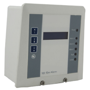
A fixed single point alarm unit that meets the requirements for economic and reliable monitoring of gas levels in a wide range of environments from commercial premises through to heavy industrial applications that may require hazardous area sensing.
The CTS101 may be utilised as a standalone unit or as an addressable sensor forming part of the CTS Combi CANbus addressable network system and therefore offering the features of our most advanced system.
Typical monitor locations are – public buildings, boiler plant rooms, swimming pools, water treatment works, H&V control systems, manufacturing and process plants.
Specifications
Data logging
Three alarm stages + relays
4-20mA analogue output
Weather proof
Back lit alpha numeric full status display
Front panel access to set up and maintenance para meters
Internal or remote sensor options.
This system is also available in panel mount version.

Aspirated sensor option

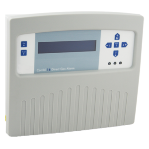
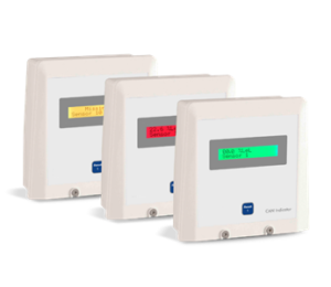
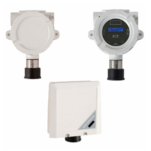
A fixed gas sensor that meets the requirements for economic and reliable monitoring of gas levels in a wide range of environments and applications. Initially designed for the monitoring of gases within cabins, enclosures and cabinets the addition of an optional mains supply input expanded its use into conventional areas of gas detection covering boiler plant rooms, gas meter houses, battery charger rooms and many other commercial and light industrial applications.
Specifications
Flammable, Oxygen or Toxic Gases
Compact size
Single stage alarm
Alarm relays
Alarm Sounder / LED
Digital display
Wall or panel mount
4~20mA analogue output
IP65
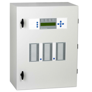
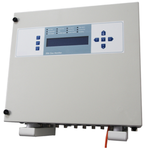
Available as a 16 direct sensors system, 64 addressable sensors or 80 combined direct & addressable sensors.
The Combi has been designed to operate in the full range of environments from commercial premises through to heavy industrial applications which may require hazardous area sensing.
Typical monitor locations are – public buildings, car parks, tunnels, breweries, boiler plant rooms, water treatment works, H&V control, manufacturing, process plants, horticulture, hotels, offices.
Specifications
Sensor points
1-64 addressable – CANbus – and/or
16 direct 4~20mA
Measurements
Combustible Gas – L.E.L., % vol
Toxic Gas – ppm, % vol
Oxygen – % vol – Depletion/Enrichment
Refrigerant – ppm
Any 4~20mA transmitter
Indicators – control unit concentration
Dot matrix LCD 4 line 40 character – indicating sensor
location, gas type, (rising or falling alarms), alarm status,
system fault, sensor line fault, sensor fault, inhibit,
real time clock, event memory
Red LED – global alarm, Amber LED – global fault,
Amber LED-inhibit
Outputs
8 user selectable zone/voting – with NE/ND option
and delay to de-energise
Relay contacts – 2 D.P.C.O / 6 S.P.C.O. rated
@ 5A-230v AC
Factory set 1 common low alarm D.P.C.O or group 1
1 common high alarm D.P.C.O or group 2
1 common overrange S.P.C.O or group 3
1 common fault alarm S.P.C.O or group 4
4 user selectable S.P.C.O groups 5 to 8
General alarm relay – resettable S.P.C.O. for sounders etc.
Optional – 2 x 32 relays – first 16 programmable
with pattern/event with NE/ND options and delay to
de-energise – 48 are single event
Optional – remote addressable 4 way relay unit
RS232 data log – event log
Modbus – RS485 x2
Combi Soft: full data logging /management tool – option.
Individual sensor logging – intervals 1-60 mins storage
readings 2880
Audible alarm
Alarm/Fault – permanent mute option
Power
230/115v AC or 24v DC ±15%
Control unit 7.5w quiescent 17w full alarm
Sensor – 1.25w
Internal power supply: 20 sensors max. 21+ sensors –
11A/24vDC Auxiliary Power Pack required C1541/C1293
This system is also available in 19” Frame for industrial applications.


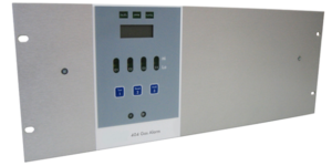
The CTS404 has been designed with features that provide an effective response to the detection of gas hazards in a wide range of environments, from commercial premises through to heavy industrial applications requiring hazardous area sensing. Typical monitor locations are public buildings, boiler plant rooms, swimming pools, water treatment works, H&V control systems, manufacturing and processing plants.
Specifications
Versatile System Configuration
Flammable, Oxygen and Toxic Gases
1 to 4 sensors
Plug in sensor channel cards
Two alarm stages
Selectable alarm relays
Analogue 4-20mA output
Delay to alarm option
This system is also available in 19” Frame.

The CTS Defender gas leak detection system features remote sensors connected to the main control unit via a single 3 core cable. The control unit is of an advanced design using the latest technology and provides a high integrity system whilst enabling a significant cost saving over conventional gas alarm systems. Up to 64 sensors can be connected to this controller (with additional power supplies). Four zones are covered with 16 sensors/zone. This system is very different from other multi sensor systems. The alarm levels are pre-set with standard alarm limits. However, if non-standard alarm levels are required, request needs to be made when placing order.
Standard sensors for use in commercial and light industrial applications such as laboratories, workshops, boiler plant rooms etc are available for monitoring toxic, flammable or refrigerant gases.
Specifications
Single 3 core cable for multiple sensors
Sensors pre-set and tested
Toxic/Flammable/Refrigerant Sensor Combination
Standard Alarm Unit 1 – 16 Sensors
Two Alarm Levels – with options
Four zone indicators
Individual sensors with audible visual alarms + relay – optional standalone
Connect directly to the CTS Combi System as 4 direct zones
Designed for ease of installation
System easily extended
Off the shelf system
The CTS305 system is designed to monitor gas levels from a number of sample-points, targeted at situations where the positioning of conventional gas sensors may not be practical. This may be due to equipment security, cable routing, access for detector head installation/maintenance, harsh environment or a cost effective means of monitoring designated hazardous areas, typically – tunnels, marine applications, underground/high level voids, process control, landfill, multi storey car parks, brewing, horticulture, superstore multi refrigeration units, Bio-fuel storage compounds.
Specifications
1-48 sample points
Monitor up to 8 gas types
No sample line purge delay
Wide range of sensor types
4 line alpha/numeric display
Selectable sample line sequence
Display of each sample line location
Easily installed and maintained
Full indication of all operations
Event logging / Modbus / RS232 / RS485
Line blockage and pump fail monitoring
Variable sample time for optimum cycle time
High integrity, comprehensive self-check fault monitoring
Centralised one man calibration offers minimum running costs
Split system operation – optional
Remote control panel – optional
Line blockage, blow back – optional
LED/text indicator panel – optional
Hazardous area operation – optional
Auto flood cut off – optional
Enclosure internal gas monitoring with automatic system shutdown – optional
Sample line multiplier – optional
The CTS306 system is designed to monitor gas levels from a number of sample-points, targeted at situations where the positioning of conventional gas sensors may not be practical. This may be due to equipment security, cable routing, access for detector head installation/maintenance, harsh environment or a cost effective means of monitoring designated hazardous areas, typically – tunnels, marine applications, underground/high level voids, process control, landfill, multi storey car parks, brewing, horticulture, superstore multi refrigeration units.
Specifications
1-20 sample points
No sample line purge delay
Wide range of sensor types
4 line alpha/numeric display
Selectable sample line sequence
Display of each sample line location
Easily installed and maintained
Full indication of all operations
Event logging / Modbus / RS232 / RS485
Line blockage and pump fail monitoring
Variable sample time for optimum cycle time
Monitor up to 2 gas types, 4 as special build
High integrity, comprehensive self-check fault monitoring
Centralised one man calibration offers minimum running costs
Split system operation – optional
Remote control panel – optional
Line blockage, blow back – optional
Hazardous area operation – optional
Auto flood cut off – optional
Enclosure internal gas monitoring with automatic system shutdown – optional
Sample line multiplier – optional


- Operates with sensors or the combi system
• Two modes of operation – indicator/repeater
• 1~15 Panels / system
• 1~64 Sensor grouping
• Traffic light display
• Simple network connection and setup
• Menu options
The CAN Status Indicator may be used as a remote indicator warning panel, providing visual and audible alarms or by menu selection, used as a repeater unit giving details of individual sensor readings and alarms from the selected sensor group.
Specifications
Communications
4 wire addressable CANbus – Combi system
Indicators
Normal – Green display screen
Repeater mode:
Concentration | Gas type | Sensor identification
Indicator mode (menu option)
Text – SAFE
A1 (low alarm)
Red screen flashing 1 second + sounder
Repeater mode:
Reading | Gas type | Sensor identification | Alarm status
Indicator mode:
Text – LOW ALARM
A2 (high alarm)
Red screen flashing 0.5 second + sounder
Repeater mode:
Reading | Gas type | Sensor identification | Alarm status
Indicator mode:
Text – HIGH ALARM
A3 (overrange alarm)
Red screen flashing 0.25 second + sounder
Repeater mode:
Reading | Gas type | Sensor identification | Alarm status
Indicator mode:
Text – OVERRANGE ALARM
Fault
Amber screen flashing + sounder
Repeater mode:
Fault status | Sensor identification
Indicator mode:
Text – FAULT

The Status Indicator is a remote module lending itself to a wide variety of warning and alarm applications.
The module provides three user selectable levels of alarm, each having varying audible tones with ‘text selectable’
illuminated window indications. The sounder may be muted at any time with the flashing LED indicators going
constant but remaining lit until the alarm condition has cleared. Three relays are available for further repeater
or control actions, these relays may be selected to reset with the sounder or remain on with the indicators.
Specifications
Power Supply
10~30vDC 24v nominal
Optional 115/230v AC (D box)
Power – full alarm 120mA @24vDC
Quiescent – 10mA
Alarm Signal
5 to 30v + DC
Inputs
4 inputs – 3 alarms and fault
Indicators
Long Life High Power LED’s
Normal
Two Green LEDs – ON (bottom window)
turning off with any alarm
Option – permanently OFF
Alarm 1
Single Red LED flashing (bottom window)
Green LEDs – OFF
Sounder – intermittent
Alarm 2
3 Red LEDs flashing (middle window)
Sounder – warbling
Alarm 3
5 Red LEDs flashing (top window)
Sounder – constant
Fault indicator
2 Amber LEDs (bottom window)
sounder intermittent
Sounder Output
87dBs @ 1 metre
Mutable or permanent isolate option
3 Relay Outputs
Volt free – SPCO 3A/230vAC
Link option for reset or latched
Other
Instruction sheet C1285
Remote reset/mute contacts –
N/O
Sounder automatic 10 minute time out
following each new event
Manual test – indicators, sounder & relays
Weight 0.45kg
Enclosure
ABS flame retardant FR40
Lid Screws M4-SS
Protection – IP64 (weather proof)
Finish – Signal White RAL 9003
Entries – Rear 5-20mm Ø 2 slot knock-outs,
Base – 20mm plug, sides, top, not specified
Mounting
Stand offs – M4 or No.8 screws
Drill at (C) when stand offs removed
Conduit box – drill at (A) 4.5mm
Surface mount box – drill at (B) 4.5mm
Window Text
Standard selection/customised/foreign C1263
Specifications
Power Supply – 230/110V AC and/or 24V DC
Power consumption max – 15 Watts
Indicators:
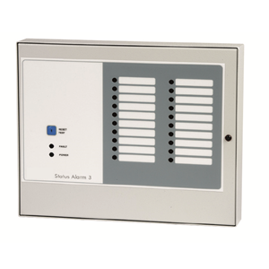
Alarms (20 off) Red LED’s Conditions: Alarm mode – Flashing Accept mode – Constant
Fault Alarm Amber LED
Power Green/Red LED Conditions: Mains On – Green State Mains Fail – Red State (battery back-up mode)
System Test – Stage 1 Alarm LED’s – ON Stage 2 Alarm relays – ON
Outputs – Alarm Relays (1) 3 sets S.P.C.O.(Rating 5A 230vAC) Latched until alarm reset (option – not resettable until signal has cleared – factory setting) Fault Relay – Set S.P.C.O Rating 5A 230v AC Mains Fail Relay – Set S.P.C.O Rating 5A 230v AC
Audible Alarm – Conditions: Gas / Fault Alarm (permanent mute option)
Signal Inputs – 20 way +24V DC (6 outputs) Field contacts, closing for alarm (20 inputs) Field contacts, closing for alarm Fault (1 input) Option at manufacture Alarm field contacts opening for +24V maintained alarm (loop failure monitored) connect jumper JP1-JP20 for unused inputs
Miscellaneous
Enclosure Wall mount – steel enclosure IP52 314W 264H 55D Cable entry Base or rear Field terminals 2.5mm Remote reset 2 wire – N/O Remote sounder 2 wire – 24v DC
Options
Channel Alarm Relays Add on board – 1 relay per channel
(Also available with Infra-red sensing technology)
All Gas types Available
• Explosion proof
• Rugged and reliable
• 3 alarm points
• CANbus 4~20mA outputs
• Wide range of gas types / sensors
• Non-intrusive adjustment magnets
• Back lit alpha numeric full status display
• Addressable or stand-alone
• Hyper terminal communications / RS232 – live data and
set up with 232 adapte
• One man calibration
• 2 alarm relays plus fault relay or 3 alarm relays
• Data logging
Specifications
Certification
Explosion proof ATEX IECEx
112G Exd IIC T6-T3 Gb
112D Extb IIIC T85˚C Db
Power Supply – 15 to 30vDC 24v nominal
Outputs – 3 wire 4~20mA / 4 wire CANbus
Relays – Low alarm S.P.C.O / High alarm S.P.C.O / Fault alarm S.P.C.O
Rating – 0.5A @30vDC
Inhibit option during servicing
Logging – Intervals – one minute to one hour / Storage – 2,880 readings
Display – 2 line alpha numeric back lit status display: gas type, concentrating units, alarm levels, alarm status, low/high/over range), sensor ID, inhibit
Indicators – Alarm – Red LED / Fault – Amber LED (flashing when in inhibit)
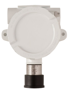
Housing Material – Copper free aluminium alloy, optional stainless steel
Finish – Chemical resistant epoxy paint / Optional – Marine grade finish / Sensor material – Stainless Steel 316516
Ingress Protection – IP63 + weather shield IP65
Cable Entry – 2 x M20 – 1.5 pitch – alternatives 25mm – 3/4 NPT
Weight – 1.6kg
Temperature -15˚C to +55˚C
See certification for Exd use
Humidity – 0 to 99% RH non-condensing
All Gas types Available
• Explosion proof
• Rugged and reliable
• CANbus / 4~20mA outputs
• Optional 2 alarm relays plus fault relay or 3 alarm relays
• Wide range of gas types / sensors
• Addressable or stand-alone
• Hyper terminal communications / RS232 – live data and set up with 232 adapter
• One man calibration
• Data logging
The XDI-F1 Gas Sensor is capable of utilising a wide range of sensor cell types offering an unmatched number of gases that may be monitored. Standard 4~20mA signalling with CANbus address enables the sensors to be networked via the CTS Combi control system or customer preferred monitoring systems.
Specifications
Certification
Explosion proof ATEX IECEx
112G Exd IIC T6-T3 Gb
112D Extb IIIC T85˚C Db
Power Supply – 15 to 30vDC 24v nominal
Logging – Intervals – one minute to one hour
Storage – 2,880 readings
Outputs – 3 wire 4~20mA / 4 wire CANbus
Optional relays – Low alarm S.P.C.O / High alarm S.P.C.O / Fault alarm S.P.C.O
Inhibit option during servicing
Rating – 0.5A @30vDC
Housing Material – Copper free aluminium alloy, optional stainless steel
Finish – Chemical resistant epoxy paint / Optional – Marine grade finish
Sensor Material – Stainless steel 316S16
Ingress Protection – IP63 + weather shield IP65
Cable Entry – 2 x M20 – 1.5 pitch – alternatives 25mm – 3/4 NPT
Weight – 1.6kg
Temperature -15˚C to +55˚C
See certification for Exd use
Humidity – 0 to 99% RH non-condensing
Our hazardous and safe area sensors for flammable, toxic/oxygen and refrigerant gasses